Truss Designing/Breaking
Explanation
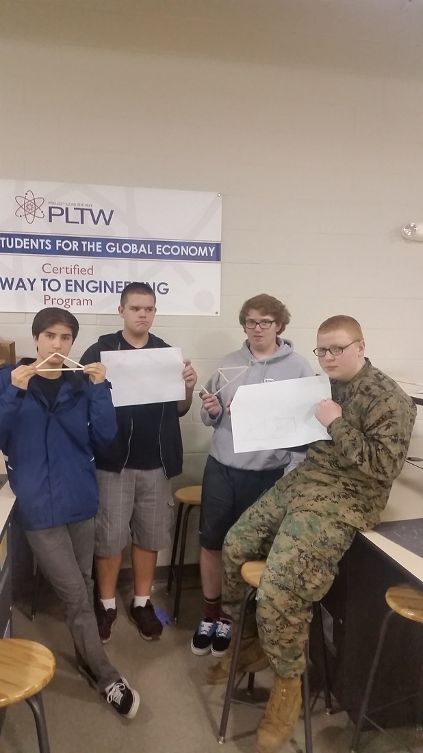
In this project we were tasked with the problem to create 2 separate trusses following the designs given to us, calculate forces of compression and tension, break the trusses, next we created free body diagrams of each truss, and finally we calculated the forces to break the truss and its efficiency.
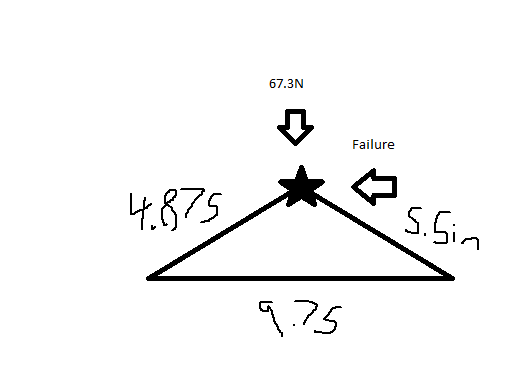
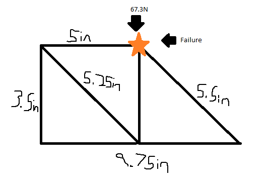
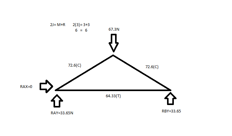
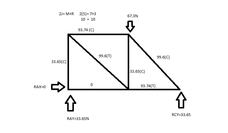
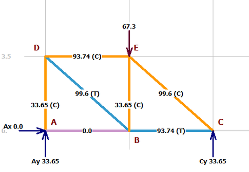
Sketches
|
|
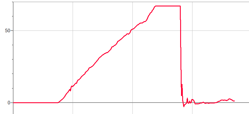
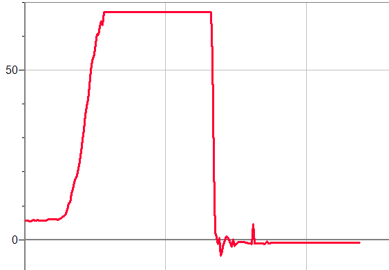
Graphs
|
|
Videos
|
| ||||
Efficiency

Truss 1 Calculation

Truss 2 Calculation
Conclusion Questions
a. Explain why you think failure occurred at the truss member where it did. Did your truss fail at the member that your calculations revealed as undergoing the most stress?
The failure occurred at the truss members that were closest to the load or pressure being put on the truss most likely because they were receiving the most force out of the other members, and the calculations showed that the members touching the point of the point of load were receiving the most compression forces.
b. If given a chance to redesign your truss after testing, what changes would you make?
If I were to redesign the first truss I would put a support in the middle of the triangle piece to push force out towards the base, and on the other truss I would switch the diagonal in the square so that it was facing the other way and it would send force directly to the pin support.
