Toll Booth
Packet
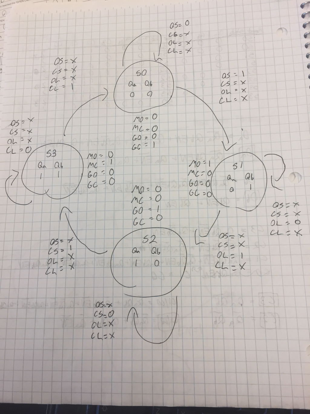
State Graph
Transition Table

Simplified Logic Expressions

The input variables are the inputs for the D Flip-Flops and are used to determine what buttons or switches are being being pressed, and when one is pressed it will send a specific signal to each Flip-Flop. The outputs detect combinations of signals so that power can be sent to the motor to raise or lower the toll booth's bar. The states determine what stage the toll booth will be on and they can be set to remain at a stage, and there are four states where the toll booth is up, down, going up, or going down.
The process we are simulating with the toll booth is a standard on and off switch that can apply to most electronics. We are simulating a system that will turn on with a button press and raise the the bar to a certain point so that a car can pass by, and the system must also be able to activate with another button press and lower the bar back to its original location.
The process we are simulating with the toll booth is a standard on and off switch that can apply to most electronics. We are simulating a system that will turn on with a button press and raise the the bar to a certain point so that a car can pass by, and the system must also be able to activate with another button press and lower the bar back to its original location.
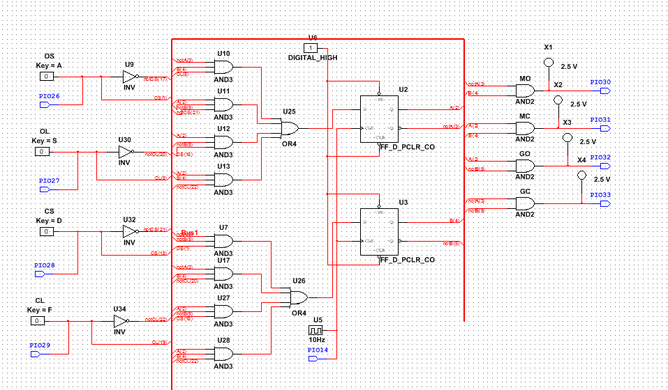
PLD
Conclusion
Our design process for the project began by completing the packet for toll booth project and building the actual toll booth. To complete the packet we used the PLTW website and the power point about state machines. We completed the information that we had to fill in to the charts then we began to create the state graph in our engineering notebooks to set up the states, inputs, and outputs for the toll booth circuit. Next we created the transition table that showed the detailed input and output codes for each state. Then we found ans simplified the Boolean algebra expressions that represented the inputs and outputs of the toll booth circuit. Our next step in the design process was creating the PLD on Multi Sim, and to create it we just modified inputs and outputs of the state machine from the previous activity. When we uploaded the circuit to the board we had wired it correctly and our PLD worked correctly, but we did not use the power box. By the time we learned that we should have used the power box our toll booth was dismantled by the other class and we took apart our circuit to move onto the next project. This project was similar to the state machine project because it is a very similar design, but it takes the process further by implementing the design onto a circuit board. This project and others have helped me to read schematics because they have been good practice to understand basic circuits on the schematics, and they have also taught me how to create and read new types of circuits like state machines. Reading a schematic now when compared to the start of the semester is vastly different because before I had no knowledge about any of the gates or chips that we use in our circuits, and before I did not understand how any of the wiring and circuits functioned. If I were to do the project again I would make sure to test the tollbooth using an external power supply because the internal power supply that comes from the myDAQ is not powerful enough to activate the VEX motors and switches so the toll booth can function.
