Beginning
The goal of the project was to take our understanding of logic gates and Flip-Flops to simulate the mechanics of a copier or printer that detect when a paper is jammed in the machine. The constraints of the project are the use of an LED when the paper is jammed then clears when the paper is gone and to use a buzzer that turns on when a paper is jammed but does not turn off until a button is pressed.
|


|
Circuits
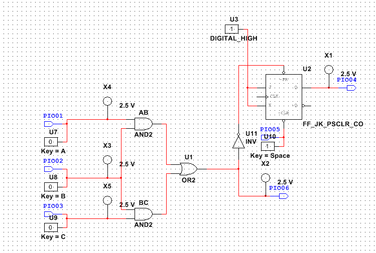
To build the circuit we needed to use 2 AND gates, an OR gate, an Inverter, LEDs, and a J/K flip-flop. The Inverters at the start are used so that when the light detector does not receive power, it will sned a signal to the AND gates. The AND gates are implemented to detect when two adjacent lights detect a paper is blocking or is jammed in the copier, and the OR gate sends a signal to the flip-flop and LED whenever one of the AND gates activate. When power goes out of the OR gate the LED will activate and the J/K flip-flop will also start a continuous clock that is not able to be stopped until the CLEAR is activated.
There are no resistors on the circuit because we did not implement it onto the actual circuit, but the resistors would be implemented so that the power that is input from the light sensors will be reduced so that it does not overheat or fry the circuit. The combination logic or AOI logic is used to detect when there is a paper jam by using an AND gate to check when two adjacent lights are blocked and an OR gate send the signal to J/K flip-flop. The flip-flop is used in the circuit to take power and output continuous power to the buzzer no matter what the input is and can only be turned off through a clear. The LED will go off once the paper is removed so when the AND gates turn off, but the buzzer stays on because it needs to manually cleared as the flip-flop is outputting continuous power.
Conclusion
This project differs from the others as we are no longer using and manipulating different types of counters to count up and pause or reset, and now we are using simple logic gates such as AND and OR to output power to LEDs. The project is also different because we are no longer using the clock of the flip-flop and instead we are using the preset and clear function. In this project I have learned how to create an infinite loop on flip-flops, how to use a flip-flop without using the clock, and how it is important to know the difference between a J/K flip-flop and a D flip-flop.
