Engine Mount

iTeam Members: Michael and Nathan
Project Description: As a group we had to assemble an engine mount using the given pieces and test forces that are applied to the structure. The firewall had to be grounded to be stable, the structural members must be fixed to the firewall , the engine must weigh 250lb, the structure will be tested under 6G and -3G, the structural members must be 1 and 1/2 inch ANSI pipe, and the members should be mitered. The purpose of this project is to determine the stress that is put on the airplane's frame when maneuvering and how the stress affects the frame of the engine. By applying the forces to the engine mount we can determine how the metal will be displaced and compress or stretch due to the forces applied. During the project we had to use all the skills we learned to make the engine mount efficient like choosing materials and mitering the correct surfaces.
Procedure: To prepare for the project we completed one assignment where we identified forces upon materials and we identified the properties of possible materials for aerospace that were efficient and strong in compression and tension like steel, aluminum, wood, and concrete. The other two assignments we completed taught us how to use the tools that are available in the inventor program to assemble parts by cutting out parts of the material or fixing the parts to each other. To design the engine mount on inventor we exported the provided file onto an assembly, then we extruded the members to be 1 and 1/2 ANSI Pipe made out of austenitic steel. Next we fixed the the structural members to the 7 points on the the firewall and mitered every member to each other. Finally we trimmed each member to the face of the engine mount points to cut off the extra parts of the members.
Solution: To test the forces of the frame we applied forces to each engine mount point: for the -3G test we applied 250lbforce in the upwards direction, for 6G we applied 750lbforce downwards on the points, and for the 1G test we only had gravity acting upon the frame. To access simulation we went to frame analysis then the simulation to see the displacement of the frame under each stress. The frame design meets the constraints as the structure followed the requirements for material and size, we followed the guidelines for adjusting the firewall and members, and we successfully tested the frame under each of the given G-forces. We decided to use the austenitic steel as our structural members because of its high tensile and compression strength as well as its ability to withstand the high temperatures near the engine of the airplane.
Report
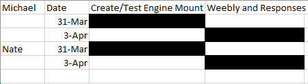
Gantt Chart
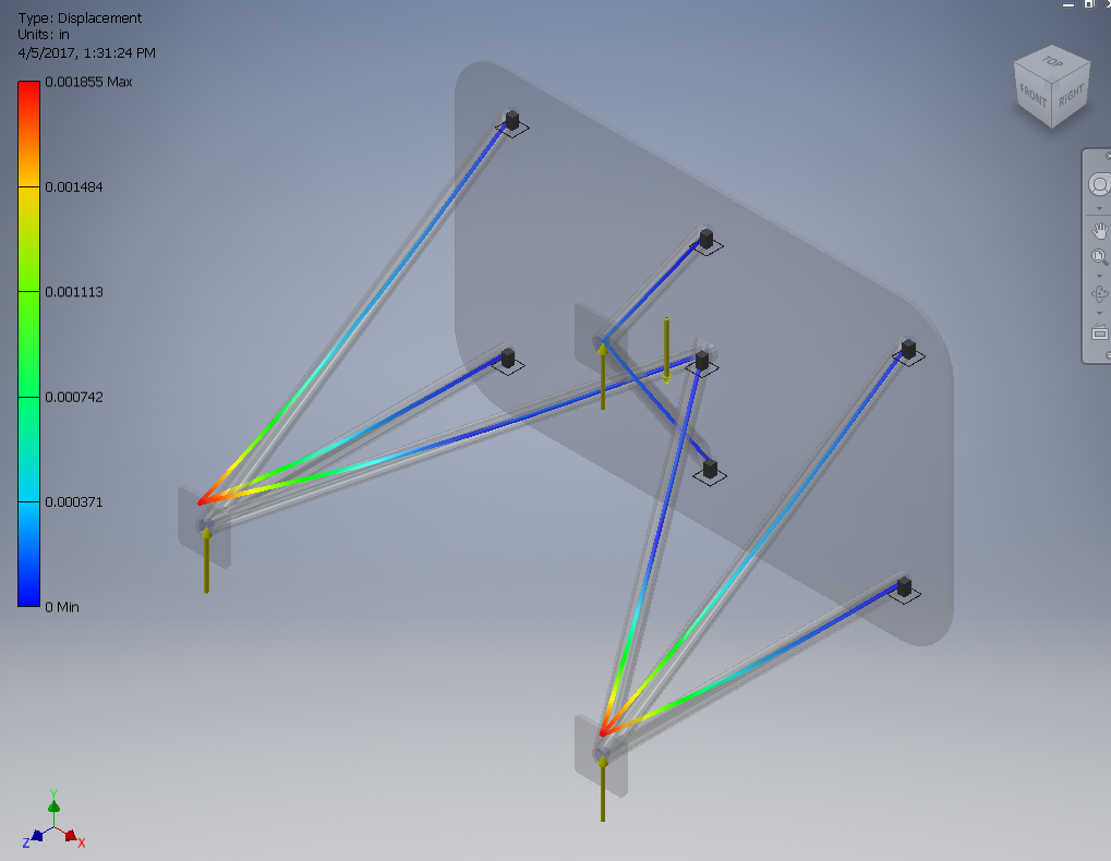
Frame under -3G showing that the frame would bend upwards due to descending in the plane quickly and the engine pulling up on the mount

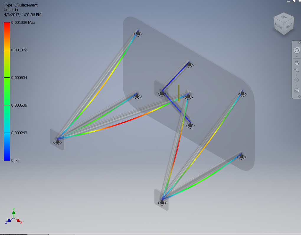
Frame under 6G showing a lot of force pulling down on the structure due to the high G-force acting upon the frame
Frame influenced by only Gravity showing only displacement downwards in the middle of the members
Conclusion Questions
Weebly Conclusions
We learned very variable resources to use involving inventor while completing this project. Some of those resources we learned were ways to edit the engine mount like the mitering tool and also how to apply forces to the fixed constraints. We both evenly contributed to this project. We both worked on building the engine mount on inventor so we could finish it together and it could get done faster. Then on the weebly, we are splitting up the work. We are splitting up the questions and deliverable on the weebly, and we are going to do the report the same way. I believe the frame generator tool is very useful in aerospace engineering as it allows you to test all different kinds of forces that will be faced with while actual flying the plane. The frame generator allows you to see if your engine mount will be safe enough to be able to take up into the air. It also allows you to change your material and size very easily, and it determines the forces very quickly without need for calculations of the displacement of the frame.
Conclusions on the worksheet
1. I predicted that the critical area of the engine mount would be located in the center structural members, but the analysis showed that the outside members take most of the stress and pressure from the G-forces.
2. Additional loading constraints to be considered by the designer include the weight of the fuel that is running through the engine, the weight of the oil inside the engine, and the weight of the coolant in the engine.
