60 Second Timer
Project Overview
The timer project has similar goals to the DMV Counter project, but it expands upon the design of the counters to use different variations. The 60 Second Timer project teaches that the outline for the counting circuit can be modified to achieve different goals because the only changes required were to change the types of integrated circuits.

PLD Circuit
The 60 Second Timer and the DMV Counter projects are very similar because they both use integrated circuits that function as counters to count to a specific number and reset or pause. However, the projects vary because they require the use of different styles of counters that are set up and detected differently. The projects teach different skills because the they use the different types of chips as well as different clock setups.
Conclusion
1. Asynchronous and Synchronous circuits are differentiated by the input to the clocks on each Flip-Flop. On Synchronous circuits all the clocks are linked to an external source and activate simultaneously, but Asynchronous circuits have only the first Flip-Flop connected to an external clock and all others are connected to the previous Flip-Flop which creates a ripple delay in the design.
2. The 74LS193 and the 74LS163 chips are different in their functions and limitations. The 193 can function as an up and down counter and shows the value before the detected number, but the 163 is only an up counter and will show the detected number.
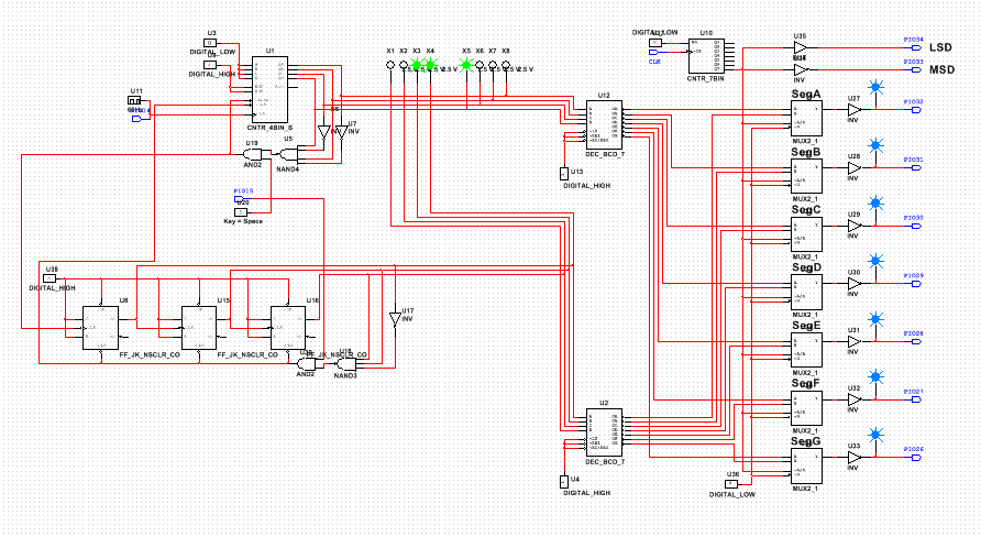
3. To begin with the project I read the problem and the constraints attached to it so that I knew what types of circuits needed to be used. The rubric specifies that the 74LS163 chip needed to used and the other counter had to be an asynchronous J/K Flip-Flop, so I uses the 163 as the ones counter and the J/K for the tens counter because the 163 could send a signal to the other clock whenever the 163 detects a 10 and resets. The J/K Flip-Flop is designed as a normal up counter with a modulus of 6, but the first clock received its input from the detection segment of the other counter. Both of the clears on the counters are linked to a singular switch so the entire circuit can be reset at any time, and whenever the J/K Flip-Flop detects a 6 the circuit will also reset and count again so that the count will never go past the number 59. Both of the outputs of the counters are connected to the predestined multiplexer which allows the the use of both segment displays. The design on the PLD mode is the same except for the components must use their counterparts and inputs had to be put on the clock and the reset switch. When implementing the design onto a breadboard I wired the pins to their corresponding locations that are shown on the multiplexer and I linked the power and ground terminals on the breadboard.
4. Similar to the previous project the circuits designed by the class were similar when comparing the counters used because we were required to use the same counters, but everybody used different techniques and logic gates to create a reset for the circuit and a reset after the count reaches 59.
2. The 74LS193 and the 74LS163 chips are different in their functions and limitations. The 193 can function as an up and down counter and shows the value before the detected number, but the 163 is only an up counter and will show the detected number.
3. To begin with the project I read the problem and the constraints attached to it so that I knew what types of circuits needed to be used. The rubric specifies that the 74LS163 chip needed to used and the other counter had to be an asynchronous J/K Flip-Flop, so I uses the 163 as the ones counter and the J/K for the tens counter because the 163 could send a signal to the other clock whenever the 163 detects a 10 and resets. The J/K Flip-Flop is designed as a normal up counter with a modulus of 6, but the first clock received its input from the detection segment of the other counter. Both of the clears on the counters are linked to a singular switch so the entire circuit can be reset at any time, and whenever the J/K Flip-Flop detects a 6 the circuit will also reset and count again so that the count will never go past the number 59. Both of the outputs of the counters are connected to the predestined multiplexer which allows the the use of both segment displays. The design on the PLD mode is the same except for the components must use their counterparts and inputs had to be put on the clock and the reset switch. When implementing the design onto a breadboard I wired the pins to their corresponding locations that are shown on the multiplexer and I linked the power and ground terminals on the breadboard.
4. Similar to the previous project the circuits designed by the class were similar when comparing the counters used because we were required to use the same counters, but everybody used different techniques and logic gates to create a reset for the circuit and a reset after the count reaches 59.
