Majority Vote 2.1.1

Project Overview
The circuit is designed to function as a voting machine for a board of directors and to be based off of the principle of majority vote. There are only 4 people who vote on the board and they include the President, Vice-President, Secretary, and Treasurer. The machine will remove paper ballots in exchange for a machine, and whenever they vote split the side that the president is on wins. The circuit is constrained as it can only use 2-input gates, but the breadboard circuit is not constrained.
Problem Conception via Truth Table & Un-simplified Expression

The truth table shows each possible circuit and the outcome of the votes, and the number of rows is correspondent to 2 to the power of the number of variables. In the case of a tie the table shows that the result is the same as the president's vote. The logic expression of the circuit is "PVST+P'VST+PV'ST+PVS'T+PVST'+PV'S'T+PV'ST'+PVS'T' = D " ,and the expression is in SOP form. I found the minterms by examining the truth table and writing out what the votes were when the vote passed, and I used the SOP format because it is easier to find from a truth table compared to the POS form.
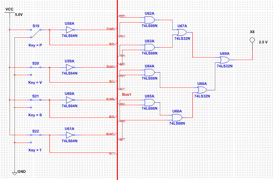
Un-simplified Circuit

The un-simplified circuit uses a bus to direct the wires to the gates so that the wires are not messy and unorganized and each minterm uses 3 AND gates while 7 OR gates are used to combine the circuit to the LED. By using the unsimplified circuit the design would require 6 AND chips and 2 OR chips because each chip only has 4 gates.
Boolean Algebra Simplification
To simplify the logic expression I began by distributing PVS out of two minterms and and simplify the two terms using the Boolean theorems into one term labeled PVS, then I used the consensus theorem on the other equations to narrow them all down to three variables per minterm. Finally I distributed each minterm to a minterm that was very similar to it, and by using the Boolean expressions I was able to remove the not variables from the expression and find the simplified expression.

Simplified Circuit
The simplified circuit uses a bus to organize the wires, but it uses far less gates for the circuit to function. Because the circuit was simplified, it will only need 5 AND gates and 3 OR gates to have the same functionality as the previous unsimplified gate. Another improvement from the simplified circuit is that it only requires 2 AND chips and 1 OR chip because the chips hold 4 gates and there are too many AND gates for only one chip.
Bill of Materials
The bill of materials for the Majority Vote circuit describes what parts the circuit uses and how many of each component are included into the final design of the circuit.
Component Quantity
Wires of assorted colors and lengths l 25
HD74LS08P Integrated AND Circuits l 2
SN74LS32N Integrated OR Circuits l 1
Breadboard l 1
Pre-made Circuit l 1
Wires of assorted colors and lengths l 25
HD74LS08P Integrated AND Circuits l 2
SN74LS32N Integrated OR Circuits l 1
Breadboard l 1
Pre-made Circuit l 1
Bread-boarding

Placing the wires into the breadboard around the first chip to set up the first 4 AND gates

Inserting all of the integrated circuits and making sure that they are connected to the positive and the ground

The completed and functional circuit
In my first breadborading experience I was trying to understand how the wires spread electricity through the system and which direction the electricity moved in, and from that experience I learned how the breadboard system works, my common mistakes, and how to troubleshoot my problems. One of my major problems that I faced was forgetting to put wires into parts of the circuit because I move onto another part of the circuit, and to troubleshoot I ran through each wire connection to make sure they were setup properly.
Final Project Conclusions
While working on the majority vote project I learned how to design both a simplified and unsimplified circuit, create and simplify a logic expression, transition the circuit design onto a breadboard, and troubleshoot any problems I had. When I started the project, I had to quickly adapt by applying the lessons that we had been learning in class to the project itself like creating truth tables and expressions for the circuit or simplifying the expressions using Boolean algebra. To go from the problem statement to the finished circuit one would have to start with brainstorming and reading the constraints, then they would begin designing the truth table for the circuit and the expression that describes both the table and the circuit design. The next step would be to create the unsimplified circuit and think about ways to simplify the design so during the next step you can simplify the circuit easier. The circuit itself and the expression would need to be simplified so that it can finally be implemented into a finished circuit design. Boolean algebra is very useful when creating and simplifying circuits because it allows you to save time when creating the actual circuit and save money by using less components for the overall circuit.
