Date of Birth Circuit
Project Overview

The purpose of this project is to give us a more in depth experience with creating circuits, simplfying expressions, and building the circuit on the breadboard. The circuit is designed to display the date of birth of the designer, and the circuit is constrained to use one NAND implementation, a seven segment display, and "Don't Care" conditions. This report will detail the process I went through to design the circuit on paper,on Multisim, and on a breadboard.
Truth Table
The truth table represents all the possible situations that the circuit can be configured into, and it also shows what will be displayed when configured accordingly. The purpose of the truth table is to show what parts of the seven segment LED are turned on and what parts are turned off.

The numbers on the left side of the table show the binary code to display the number to the right of the code, and the middle column illustrates what will appear on the LED. The columns of a through g are based off the individual lights in the seven segment display as the lights are labeled with the same letters, and a 1 represents the light being on while 0 represents it being on. The Xs in the table are "Don't Care" conditions because the values are not needed to show the date of birth and they can use any of the lights on the display.
K-maps and Simplified Logic for each of the Seven Segments


K-mapping uses an organized table of the output column of truth tables to create a simplified logic expression without Boolean algebra, and k-mapping requires the grouping of the 1s in as large of a group as possible. The k-mapping tables or ordered with the outputs of 1,2,3,4,7,8,5, then 6, and the outside labels use the different combination of 1 or two of the variables. The expressions that I found from k-mapping were in sum-of-products form, and k-mapping is used over Boolean algebra because it is faster and less prone to errors.
MultiSim Implementation
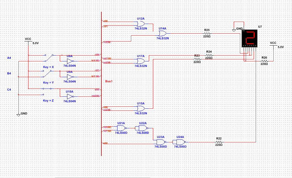
The circuit I created uses a bus to simplify the wiring process, and it uses very few gates and chips. Overall the design only needed 3 chips to function, and I used 4 OR gates, 3 Inverters, and 4 NAND gates. For my circuit I decided to use NAND gates rather than NOR gates because I did not want to confuse myself with the backwards NOR chip and a NOR implementation would require more than 4 gates. NAND and NOR gates are used as a universal chip to save money and efficiency of a design in certain circumstances as using all of the same chip is better than not fully using various chips, but in my design the NANDs increase the number of gates while keeping the number of chips the same. The seven segment displays works by connecting power or ground to the individual LEDs, and this design uses common cathode display which requires power to activate the LEDs.
Bill of Materials
The bill of materials is a chart that describes what components are used in a design and the quantity of each component.
COMPONENT QUANTITY
Breadboard+Display 1
Integrated Circuit 74LS00 1
Integrated Circuit 74LS04 1
Integrated Circuit 74LS32 1
Wires A lot
COMPONENT QUANTITY
Breadboard+Display 1
Integrated Circuit 74LS00 1
Integrated Circuit 74LS04 1
Integrated Circuit 74LS32 1
Wires A lot
Bread-boarding

Wiring the essential pieces, placing the chips, and wiring the lights that are always on

Creating the first few expressions and troubleshooting the connections

The completed and functioning circuit
The second bread boarding experience was a lot better than the first because I already knew what I was doing, so I could start very quickly and any problems I ran into I could identify and solve much faster than before. The biggest mistake I had on my board was with the Inverter chips becuase I was not using the proper gates and some of the LEDs were not activating when they needed to. While designing the board I separated the ICs so the wires wouldn't get tangled up, and I ended up using all of the gates on the chips except for some of the inverters.
Conclusion
This project has taught me how important it is to check your k-maps multiple times to make sure that it is as simple as possible, and the project helped me understand how to implement universal gates onto a breadboard design. If I were to do the project again I would make sure to color code the wires based on expression so that when I would troubleshoot I would know exactly which wires are the problem without tracing back each expression's wires. I still don't understand why a resistor is really needed in the implementation of the circuit because it functions the same with or without it, and I also don't understand what a NAND or a NOR gate does by themselves. The k-mapping process is very useful as it can be used to find simplified logic expressions faster or it can be used to check simplification using Boolean algebra.
